
Manufacturing Large Multi-Stage Telescopic Hydraulic Cylinders
Custom telescopic cylinders with 2-6 stages, outer-stage bores up to 600 mm and total strokes up to 12 m, machined, plated, assembled and tested in-house.

Eurobalt manufactures custom telescopic hydraulic cylinders of any complexity based on customer drawings or technical specifications. Our in-house capabilities cover the full production cycle: CNC machining and honing of every stage, surface coating of the plungers, welding of end fittings and mounting elements, stage-by-stage assembly and acceptance testing. This article describes how we build large, non-standard multi-stage telescopic cylinders: the production sequence, the tolerances involved, and the configuration options available to the customer.
A telescopic cylinder is, in manufacturing terms, several precision cylinders nested inside one another. Every intermediate stage acts simultaneously as a plunger (its outer surface slides and seals inside the previous stage) and as a cylinder tube (its honed bore carries the next stage). This dual role is what makes telescopic cylinder production considerably more demanding than that of a conventional single-stage unit. Cylinder design, materials and coating comparison are covered in detail in our complete guide to telescopic hydraulic cylinders; here, we focus specifically on the manufacturing process, and on why in-house control over every operation pays off.
Configuration: Stages and Type of Action
| Parameter | Range |
|---|---|
| Number of stages | 2-6 (3-5 most common) |
| Type of action | Single-acting or double-acting |
| Collapsed length | Typically 25-40 % of the extended length |
| Extension sequence | Largest stage extends first, smallest last |
| Working pressure | 140-250 bar nominal |
Single-acting telescopic cylinders extend under hydraulic pressure and retract under the weight of the load: the standard solution for tipper trucks, dump trailers and similar applications where gravity provides the return force.
Double-acting telescopic cylinders are powered in both directions. Each stage is effectively an independent double-acting cylinder nested inside the next one, which requires additional annular sealing surfaces, transfer porting and retraction sequencing. We build double-acting units for cranes, lifting platforms and horizontal installations where no gravity return exists, and design the retract circuit so the stages return in a controlled order without out-of-sequence movement.
The number of stages is a design trade-off we calculate for each order: more stages give a longer stroke from the same collapsed length, but each added stage reduces the final-stage diameter (and therefore the force at full extension) and adds a sealed sliding interface. For large custom cylinders we verify stage count against buckling stability at full extension and side-load conditions at the mounting points.
Large and Non-Standard Dimensions
| Parameter | Capability |
|---|---|
| Outer-stage bore | 90-600 mm (larger on request) |
| Total stroke | Up to 12 m for multi-stage designs |
| Inter-stage radial guide clearance | ≤ 0.07 mm |
| Bore tolerance (each stage) | ISO H8-H9 |
| Bore surface finish | Ra 0.2-0.4 µm |
Large telescopic cylinders are almost never catalogue items. Mounting geometry, collapsed length, port positions and stage diameters follow the customer’s machine, not a standard series. We machine every stage to order, which allows non-standard combinations such as an oversized outer stage with a short collapsed length, an intermediate stop position, or a custom mounting arrangement, all without the compromises of adapting a mass-produced cylinder.
Materials
| Component | Material (EN) | Equivalent (AISI) |
|---|---|---|
| Stage tubes / barrels | E355 +SR cold-drawn seamless honed tube (EN 10305-1); ST52-3 (EN 10297-1) | ~1024/1026 strength class |
| Plunger surfaces, light and medium duty | C45E / Ck45, induction-hardened (EN 10083) | AISI 1045 |
| Plungers and rods, heavy duty | 42CrMo4, quenched and tempered, induction-hardened to 55±2 HRC | AISI 4140 |
All material arrives with EN 10204 Type 3.1 inspection certificates and passes incoming dimensional and hardness checks before entering production. Honed tube is procured close to final bore size; for non-standard diameters we hone from pre-machined tube in-house.

Plunger Surface Coatings
Every sliding stage surface is coated. The coating is selected per stage and per operating environment:
| Coating | Thickness | Hardness | Corrosion resistance (ISO 9227 NSS) | Typically specified for |
|---|---|---|---|---|
| Hard chrome | 20-50 µm (up to 80 µm heavy duty) | 800-1000 HV | 40-96 h | Standard mobile and industrial duty |
| Duplex nickel-chrome | 2 layers, up to ~250 µm total | Chrome top layer over ductile Ni barrier | 500 h and above | Marine, offshore, chemically aggressive environments |
| Salt-bath nitrocarburizing (QPQ) | Diffusion layer, no dimensional build-up | 900-1200 HV | Up to ~10× untreated steel | Dimension-critical stages, Cr(VI)-restricted specifications |
| HVOF / plasma-sprayed coatings | 150-300 µm as sprayed, ground to size | Up to 1200-1400 HV | Best in class, dense low-porosity layer | Mining, dredging, extreme abrasive duty |
After plating or spraying, each plunger surface is ground and polished back to the specified diameter and finish. On a multi-stage cylinder the coating thickness is part of the inter-stage fit calculation, so plating is dimensioned into the machining plan from the start, not added afterwards.
Mounting Options

| Mounting | Description | Typical use on telescopic cylinders |
|---|---|---|
| Clevis / pin-eye | Pinned U-bracket or eye, single-plane pivot | Rod-end of tipper and trailer cylinders |
| Trunnion | Pivot pins on the outer barrel (end or intermediate position) | Underbody tipper cylinders, articulating booms |
| Flange | Rigid bolted connection | Stationary presses, lifts, vertical installations |
| Spherical bearing | Self-aligning, absorbs out-of-plane misalignment | Cap-end of long cylinders where geometry changes through the stroke |
| Cross-tube | Transverse tube welded to the barrel | Dump truck and agricultural trailer front-end cylinders |
Combinations are common: for example, a trunnion collar on the barrel with a spherical bearing at the cap end. Mounting elements are welded or machined in-house, and their position is checked against the stroke-dependent load path: on a telescopic cylinder the bending moment at the mounts changes as the stages extend, which we verify at the design stage.
Sealing System
Each stage of a telescopic cylinder carries its own complete sealing set: a primary pressure seal, guide rings (wear bands) that prevent metal-to-metal contact, a wiper that keeps abrasive contamination away from the sealing lip, and a stop ring that limits stage travel. A five-stage cylinder therefore contains five independent sealed sliding interfaces, each machined, fitted and tested individually.
Seal materials are selected per application: polyurethane for the primary seals and wipers in standard mobile duty, PTFE-based compounds for low friction and wide temperature ranges, NBR/FKM elastomers for the static seals. Guide rings are filled PTFE or fabric-reinforced composite, sized against the expected side load.

Telescopic Cylinder Manufacturing Process
The manufacturing cycle of a large multi-stage telescopic cylinder follows our cylinder manufacturing chain and includes 8 main stages:
Stage 1. Engineering and Design Review
We start from the customer’s drawings or duty specification: required force, stroke, collapsed length, mounting geometry and operating environment. Our engineers calculate the stage count and diameters, verify buckling stability at full extension, select seal and coating systems, and agree the final design with the customer before any material is ordered.
Stage 2. Material Procurement and Incoming Inspection
Honed tube (E355/ST52-3) and plunger bar stock (C45E or 42CrMo4) are purchased against EN 10204 Type 3.1 certificates. Incoming inspection covers dimensions, surface condition and hardness; certificates are filed in the order dossier for full traceability.
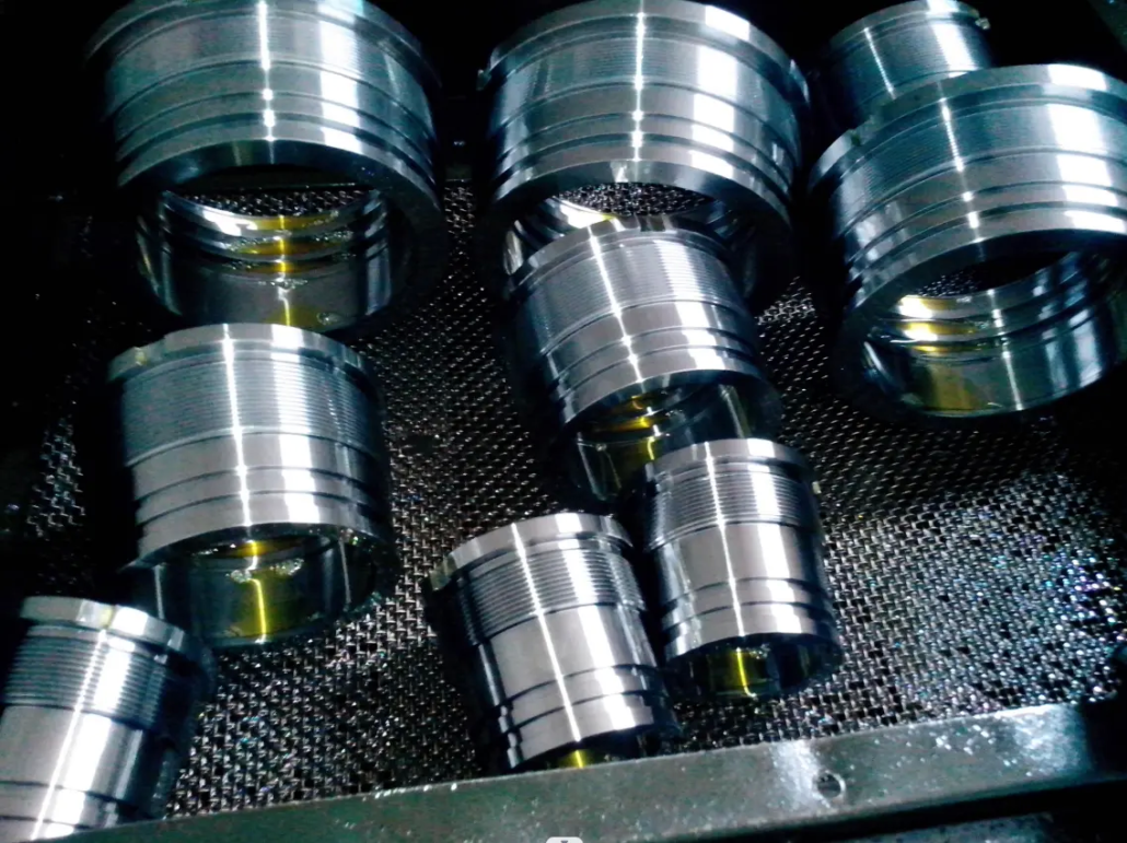
Stage 3. Machining of Tubes, Gland Heads and Mounting Elements
Each stage is machined as both a plunger and a cylinder: the outer diameter is turned and ground to the plating allowance, the bore is honed to ISO H8-H9 with Ra 0.2-0.4 µm, and the seal grooves, stop-ring grooves, gland threads and port bosses are CNC-machined. Inter-stage radial clearances of 0.07 mm or less over stage lengths of several metres set the precision bar for this operation. Gland heads (head bushes), clevis eyes and trunnion collars are machined as separate parts on the same CNC centres, then threaded and bored to their fits.
Stage 4. Surface Coating of the Plunger Surfaces
The sliding outer surfaces of every stage are hard-chrome plated (or coated with the duplex, QPQ or HVOF system specified at the design stage), then ground and polished to the final diameter and surface finish. Coating thickness is verified at multiple points along each stage.
Stage 5. Welding and Fabrication
Cylinder bottoms, cross-tubes, trunnion pins and clevis brackets are welded by qualified welders, followed by non-destructive testing of the load-bearing welds (ultrasonic or magnetic-particle, per drawing requirements). Welded assemblies are stress-relieved where the design calls for it before final machining of the mounting interfaces.

Stage 6. Seal Installation and Nested Assembly
Assembly proceeds from the innermost stage outwards. Each stage receives its seal set, guide rings, wiper and stop ring; the stage is inserted, the gland is torqued, and free movement is checked before the next stage is added. Assembly takes place in a clean area: on a multi-stage cylinder a single contaminated interface is enough to cause premature seal failure.

Stage 7. Acceptance Testing
Every cylinder is tested per ISO 10100: proof pressure at 1.5× working pressure held on both sides of the piston area, full-stroke cycling of all stages, verification of the correct extension and retraction sequence, drift (creep) test under sustained load, and external leakage inspection. Test results are recorded in the order dossier.
Stage 8. Painting, Preservation and Dispatch
The cylinder is painted to the customer’s coating specification, ports are sealed with protective plugs, exposed plated surfaces are preserved, and the unit is packed for transport in the collapsed state.
Quality Control
- Incoming material inspection against EN 10204 Type 3.1 certificates
- Dimensional control of every stage: bore diameter and roundness, plunger diameter, inter-stage clearance
- Bore surface-finish verification (Ra 0.2-0.4 µm) after honing
- Coating thickness and adhesion checks after plating/spraying
- Non-destructive testing of load-bearing welds
- 100 % pressure and function testing per ISO 10100: every cylinder, not a sample
- Full traceability: material certificates, measurement protocols and test reports filed per order
Standards Reference
| Standard | Scope |
|---|---|
| EN 10305-1 / EN 10297-1 | Cold-drawn seamless precision tube (E355 / ST52-3) for stage barrels |
| EN 10083 | Quenched and tempered steels (C45E, 42CrMo4) for plungers and rods |
| EN 10204 Type 3.1 | Material inspection certificates |
| ISO 286 (H8-H9) | Bore tolerance system for honed stages |
| ISO 9227 | Neutral salt spray testing of protective coatings |
| ISO 10100 | Hydraulic cylinders: acceptance tests |


