
Quality Control System: Predictable Results from Drawing to Dispatch
Every part we make passes through the same chain: drawing review, first sample, incoming material, stage checks and final testing. This article shows how that chain is built, what we measure with, and what the customer gets on paper at the end.
Why We Manage Quality as a Process
A supplier can inspect parts at the end and sort out the bad ones. That approach finds defects. It does not prevent them, and it says nothing about whether the next batch will be any better. We work differently. Before production starts, our quality engineers write a control plan for the specific part: which characteristics are checked, at which operations, how many pieces, with which instrument, against which tolerance. The plan is part of the production route, and a batch does not move to the next operation until the previous one has been signed off.
That is what makes the result predictable. The customer knows in advance which checks the part will go through, what documents will arrive with the shipment, and what can be requested on top. Our quality management system is built to ISO 9001, and independent verification by our customers and by certification bodies is a normal part of how we work.

Five Points of Control
Control does not live in one room at the end of the shop. It is spread over five points, and each one closes a different type of risk.
1. Drawing and requirements review
Every order starts with an engineering review of the drawing. The technical team checks that the dimensions, tolerances, material grade, surface treatment and test requirements are complete and can be produced together. Missing tolerances, contradictory references and unusual material call-outs get resolved with the customer here, before any steel is cut. At this stage we also agree the acceptance conditions: which characteristics are critical, what the sampling will be, and which certificates are needed.
2. Tooling and first sample
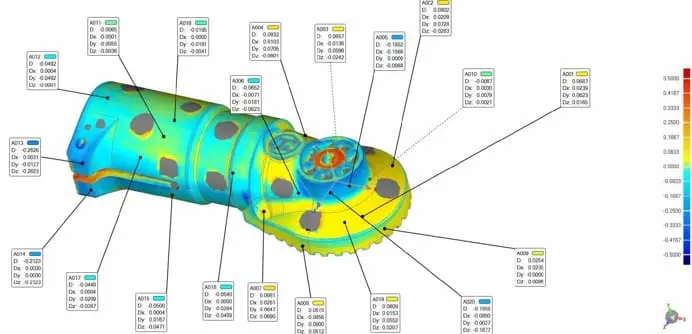
For parts that depend on tooling, such as sintered components, MIM parts, castings and cemented carbide, the first article is a separate control point. We analyse the process to find the places where complex tooling can drift, run a trial batch, and measure everything on it. For carbide, that includes a trial sintering to fix the real shrinkage coefficient for the specific WC/Co composition. For machined and cast parts, a 3D scan of the first piece is compared against the CAD model, and the colour map of deviations shows where the process needs correction before series production is released.
3. Incoming material
Material arrives with mill certificates, usually EN 10204 Type 3.1, and the certificate is only the start. Our laboratories check the material itself: chemical composition on a spectrometer, hardness, dimensions and surface condition of tube, bar and forged blanks. Honed tube for hydraulic cylinders, plunger bar stock, forged gear billets and metal powders all go through this step, and metal injection moulding feedstock is checked before the first shot. The certificate and the incoming inspection record are filed in the order dossier, so the material of any finished part can be traced back to the heat number.
4. Inspection during production
Most parts we make go through several departments: forging, machining, heat treatment, grinding, plating, welding, assembly. Each operation ends with a check against the drawing, and the parts are marked, so at any moment we know when, where and by whom a component was produced. A detected deviation is corrected on the spot and the parts are measured again before they continue. Nothing is assembled from unverified components.
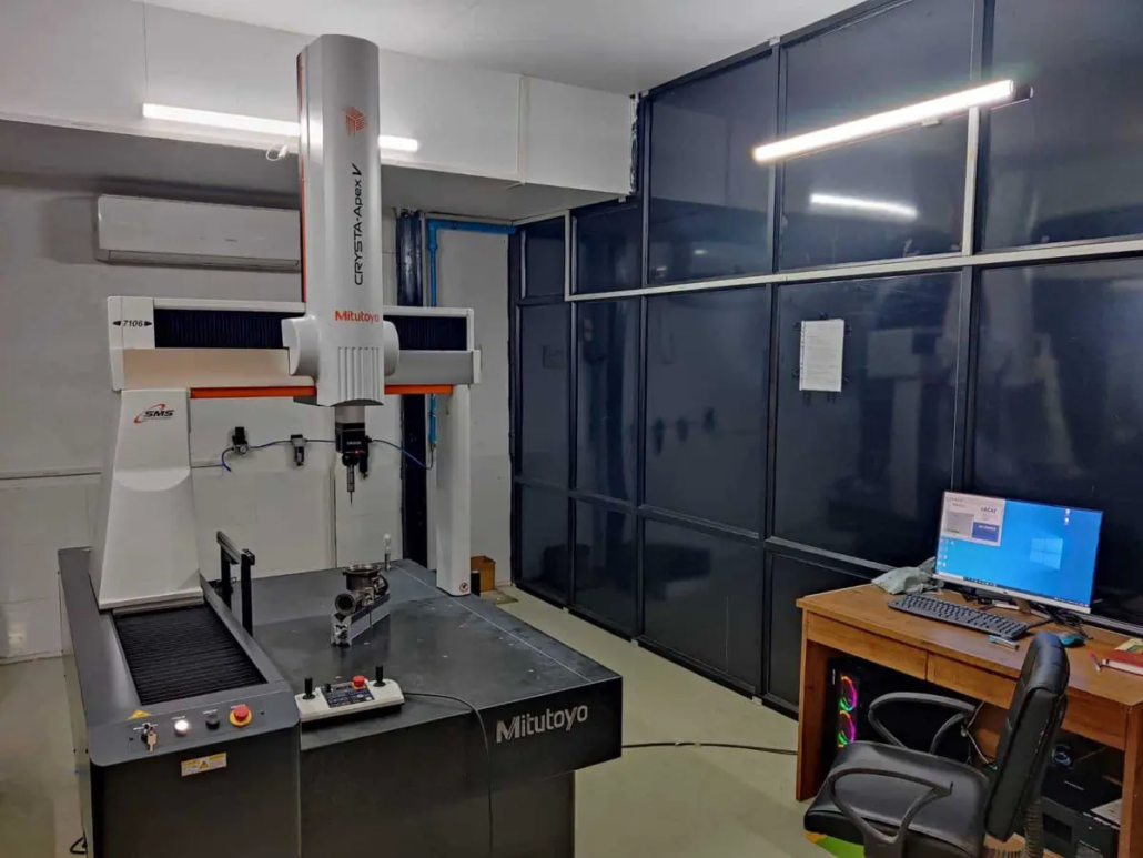
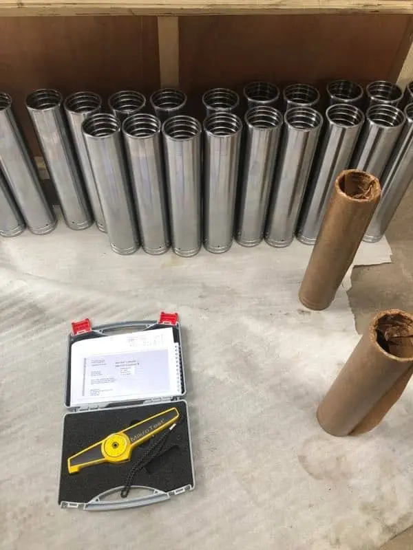
For dimensional control we use coordinate measuring machines from Mitutoyo and Zeiss with articulating probe heads, optical and video measuring machines for small and thin-walled parts, and the usual shop-floor instruments: micrometers, bore gauges with dial indicators, thread gauges, dial indicators on V-blocks for runout. Surface roughness is measured with a stylus profilometer and reported as Ra and Rz. Hardness is checked on Rockwell, Brinell and Vickers testers, and case depth is verified with a micro-Vickers traverse on a cut section where the drawing requires it. Coating thickness on chrome-plated rods is measured along the rod with a magnetic induction gauge. Every instrument is on a calibration schedule, and calibration is done in specialised metrology laboratories.
5. Final inspection and testing
Final control is not a visual check at the packing table. Each product family has its own set of tests, and for the ones where a failure in service is expensive, the tests cover 100 percent of the batch rather than a sample.
What We Test, by Product Family
| Product | Final inspection and tests | Reference standards |
|---|---|---|
| Hydraulic cylinders, including telescopic | Proof pressure at 1.5 to 2 times working pressure, tightness test on every unit, full-stroke cycling, drift test under sustained load, push and pull force on the test stand, non-destructive testing of load-bearing welds | ISO 10100, EN 10204 3.1, ISO 4287 for honed bores |
| Piston rods | Diameter, runout and thread runout on the CMM, Ra and Rz, hardness and case depth, chrome thickness, coating adhesion by thermal shock, magnetic particle inspection of the hardened zone | ISO 2819, ISO 9227, EN 10204 3.1 |
| Gears, cut and ground | Profile, lead, pitch and runout measurement, surface and core hardness, magnetic particle inspection of tooth roots and fillets | ISO 1328-1 |
| Sintered parts and sintered gears | Density, hardness, dimensions after sizing, metallurgical analysis, gear mesh test | ISO 5755, ISO 3369, ISO 4498 |
| MIM parts | Weight control, dimensional check against the ±0.5 percent tolerance class, surface finish to Ra 2.5 | ISO 22068 |
| Cemented carbide | Vickers or Rockwell A hardness, transverse rupture strength on bend bars from the same sintering cycle, density, grain size, magnetic properties, dimensions to ±0.01 mm after grinding | ISO 3878, ISO 3327, ISO 4499, ISO 2768-mK |
| Castings | Dimensional tolerance class, material and mechanical tests, machining where ordered | ISO 8062 CT6 to CT12, ST8 |
The table is a summary. For a specific part the list comes from the drawing and from the control plan agreed at the review stage. Additional tests, such as salt spray on a coating or destructive testing of a sample, are added when the customer’s application calls for them.

Three Levels of Control
Inspection inside the workshop is the first level. On top of it, a quality expert from the head office is present at the production site and controls the supplied products against our internal standards and the customer’s requirements. The third level is independent: at the customer’s request and by prior arrangement, an external organisation such as SGS carries out inspection and issues its own report.
The same three levels apply when we subcontract a special technology to one of our manufacturing partners. Our engineers review the drawing and design the tooling, we control the first samples and the batch production, and Eurobalt inspects and accepts the finished parts before they go to the customer. The customer deals with one supplier and one quality system.
Learning from Failures Before They Happen
For hydraulic cylinders we run a failure mode and effects analysis for each design. Warranty cases, transport and storage conditions, changes in operating conditions and the drawing itself are recorded in a database, and the analysis is used to remove a potential failure from the design or the process before the batch is made. Trial results, warranty history and inspection records feed back into the control plan for the next order. That is why we can offer a two-year warranty on cylinders and extend it on request.
What the Customer Receives
Predictability only counts if it reaches the customer as documents. With a shipment, or on request, we provide:
- Material certificates, EN 10204 Type 3.1, with traceability from heat number to finished part
- Measurement protocols for the dimensions listed in the control plan
- Test reports: pressure and tightness for cylinders, force measurements, hardness and coating readings
- A quality certificate with a full inspection report for the batch
- Laser marking or stamping on the part where traceability on the piece itself is required
- Spare seal kits with each batch of cylinders
A quality control report can be issued for any order. If the customer needs a witnessed test, an inspection by a third party, or a first-article report in their own format, that is arranged at the review stage and becomes part of the plan.
In Practice
A control system is only useful if it changes what happens on the floor. In practice it means three things. The customer’s engineer sees the control plan before production, not the rejection report after it. A component that has failed a check does not travel further, so a problem is found at the operation that caused it. And every batch leaves with a paper trail that allows the customer to answer, years later, which material a part was made from and which tests it passed.


